Session 2:
Working principles and limitations of land-based machinery
Introduction
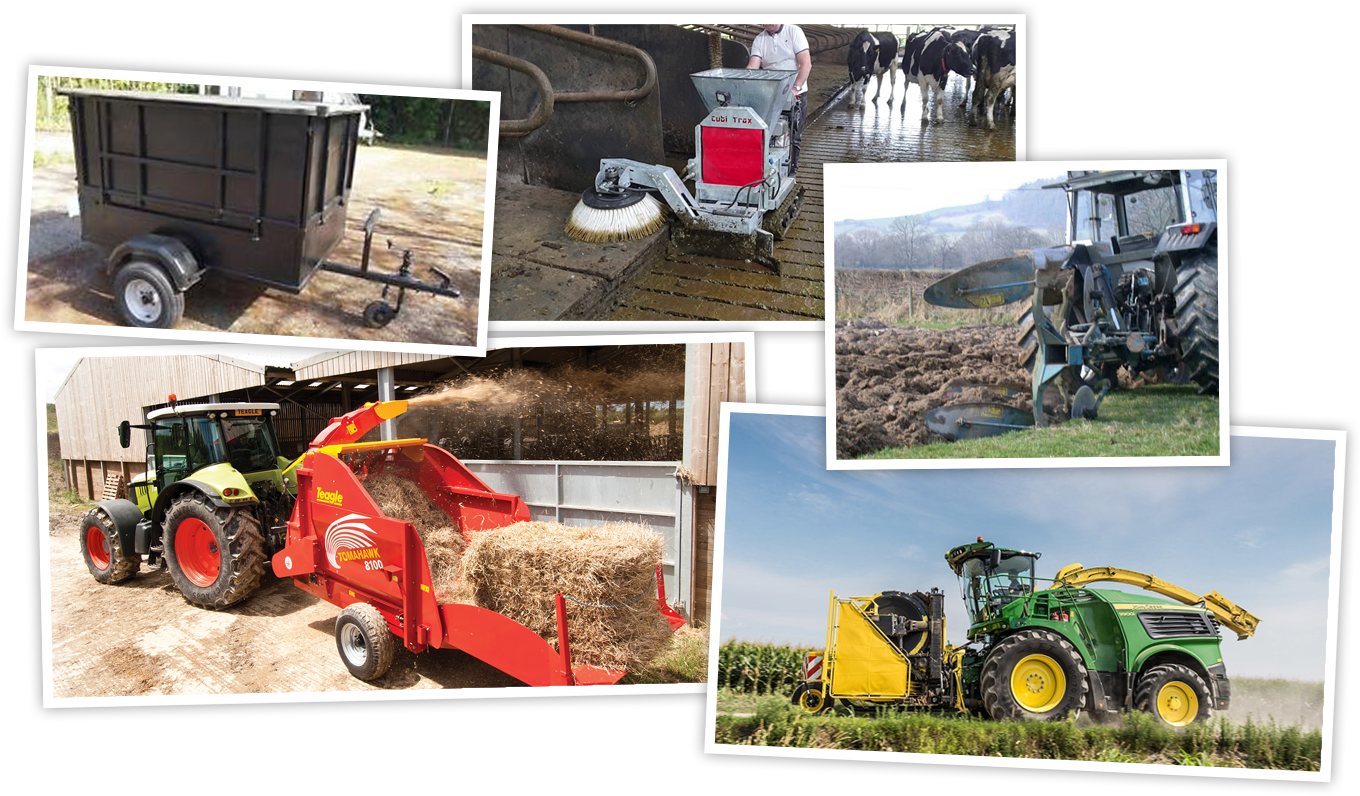
By the end of this session you will be able to understand the purpose, operating and working principles and limitations of land-based industry machinery. For example:
- Purpose built, trailed, tractor mounted, self-propelled or pedestrian
- Power source (e.g. electric, battery, spark ignition, compression ignition, PTO and hydraulic)
- Drive and transmission systems
- Cutting mechanisms
- Cutting/loading capacity or range
- Input and output ranges and levels
- Terrain suitability
- Safety features
Purpose built, trailed, tractor mounted, self-propelled or pedestrian
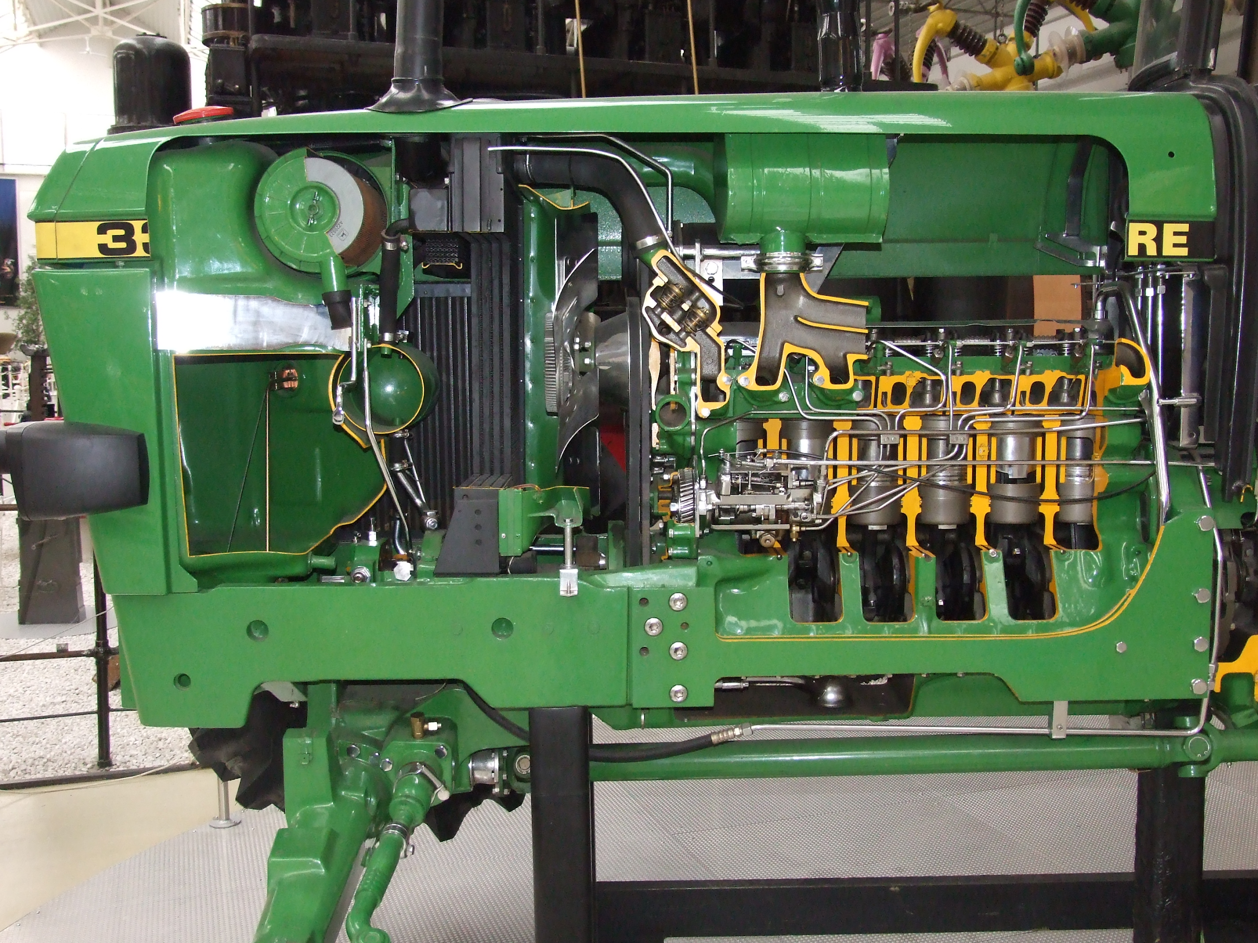
Power source for machines
For machinery to work, there has to be a power source.
There are many types:
- Electric
- Battery
- Spark ignition
- Compression ignition
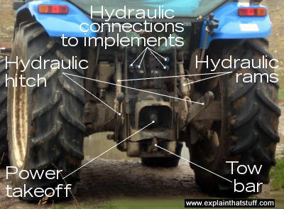
- PTO
- Hydraulic
Definitions
Hydraulic system of a tractor
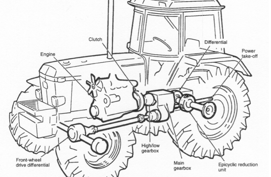
Drive and transmission systems
The transmission system of the tractor is made up of
- the clutch
- the gearbox
- the differential
- final gear reduction
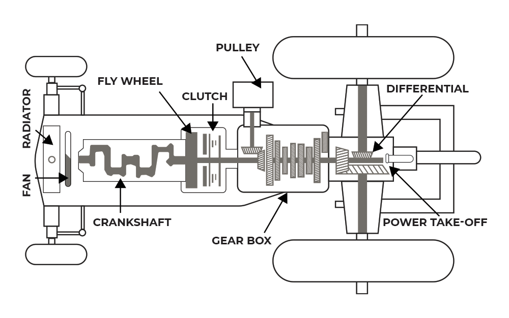
The clutch
The clutch is in the power train immediately after the engine flywheel. It is a connection device between the engine and the rest of the system. Clutches used on tractors may operate dry or run in oil (wet). The wet clutch is often multiple plate; that is, it has more than one driving disk.
Clutches may be held in engagement by springs or by over centre linkage. Hydraulic clutches are held in engagement by fluid pressure. The end of the input shaft is fitted into a bearing in the centre of the flywheel and the plate is positioned between the face of the flywheel and a spring-loaded pressure plate.
The clutch (continued)
In order to transmit the drive from the engine flywheel to the clutch shaft which goes directly to the gearbox, it is only necessary to allow the clutch plate to be gripped between faces of the flywheel and the pressure plate. The heavy spring pressure is sufficient to do this and form a solid drive to the shaft.
To release the pressure on the spring it is only necessary to press the clutch foot pedal which pushes forward the thrust bearing which in turn releases the pressure and grip between the pressure plate and the flywheel and the drive to the clutch shaft ceases.
The dry single clutch
In the dry, single clutch, the clutch is attached to the engine flywheel so that it rotates with it. A friction plate is splined onto the clutch shaft. Splines are formed by cutting rectangular shaped grooves out along a portion of the shaft.
If we have splines cut in the centre of the clutch plate, these can be mated onto the shaft so that it will slide along the shaft, yet rotate with it.
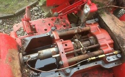
The gearbox
The main purpose of the gearbox is to reduce the speed of the drive from the engine crankshaft before the drive is applied to rear wheels of the tractor.
It will also change the speed ratio as required. The gearbox provides means of allowing the tractor to be reversed and allows the drive to the wheels to be stopped without stopping the engine by means of the clutch.
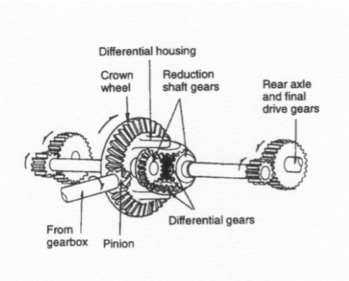
The differential
The drive from the engine comes in a straight line with the engine crankshaft, in order for the rear wheels of the tractor to be driven, it is now necessary for the drive to be taken at right angles to this line.
The gearbox output shaft extends a short distance outside the gearbox and has fitted to its end a toothed gear known as a bevel pinion.
This pinion is in mesh with another bevel gear known as the crown wheel. This achieves three things:
- changes direction of the drive
- speed reduction
- allows each drive wheel to rotate at a faster or slower rate than the other when turning corners.
The differential (continued)
To allow this to happen, the unit known as the differential is used and is directly attached to the crown wheel. The disadvantage of the differential is, for example, a tractor is ploughing, one of its wheels is usually running on a greasy surface, this can result in that wheel skidding. To overcome this, the tractor is fitted with a differential lock which will make both wheels travel together in a straight line.
Final gear reduction
All gearboxes have some form of gear reduction as the drive leaves the differential unit before reaching the wheels.
Two examples are:
- Spur reduction: This is where the half-shafts coming from the differential unit are fitted with a small spur coupled to a large spur gear wheel which is directly on the end of the rear axle.
- Epicyclic reduction: This is where the drive from the differential enters an epicyclic gear pack and the drive is reduced to the wheel speed.
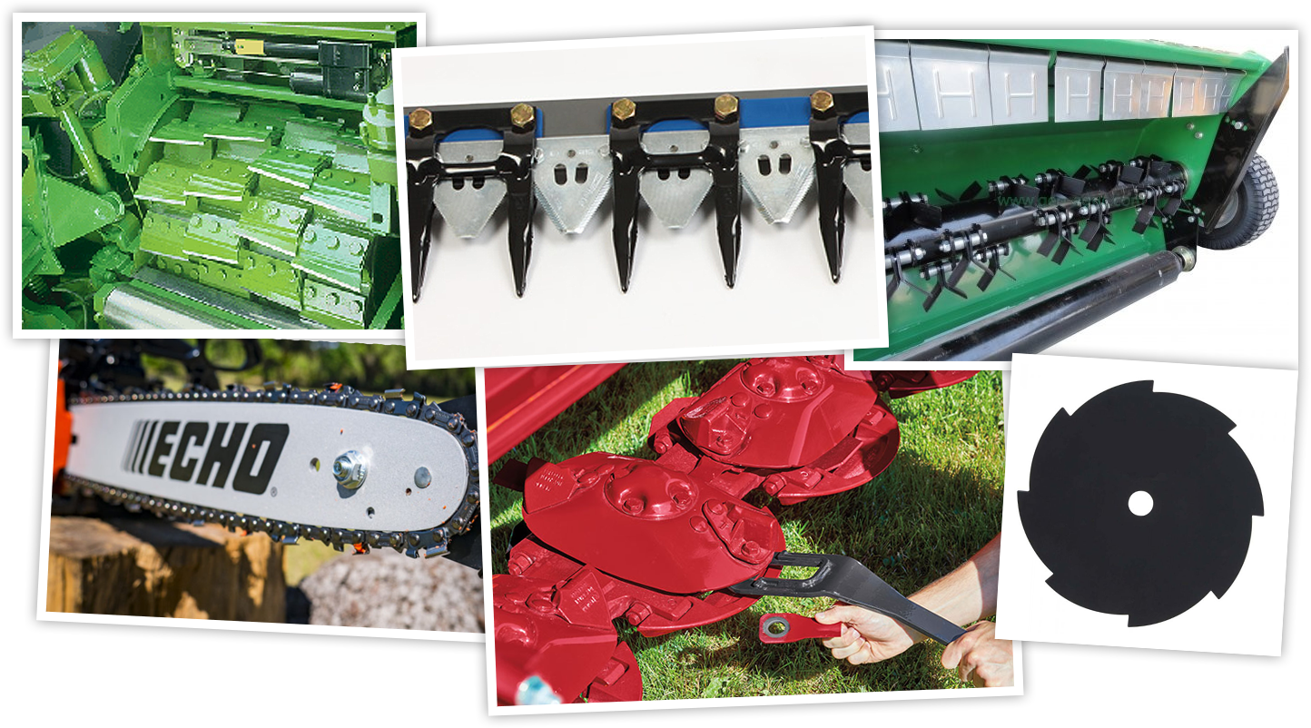
Cutting mechanisms of land-based machines
The majority of cutting mechnisms on farm machinery are involved in the harvesting of crops. Examples are:
- mowers
- forage harvesters
- chainsaws and other felling machinery
The cutting mechanism varies. It could be
- a disc
- a set of knives
- a chain
- a cutter bar
- one blade
- flail blades
All cutting surfaces have to be sharpened.
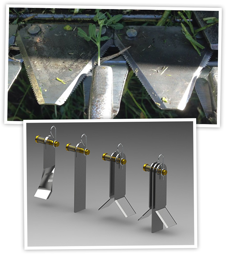
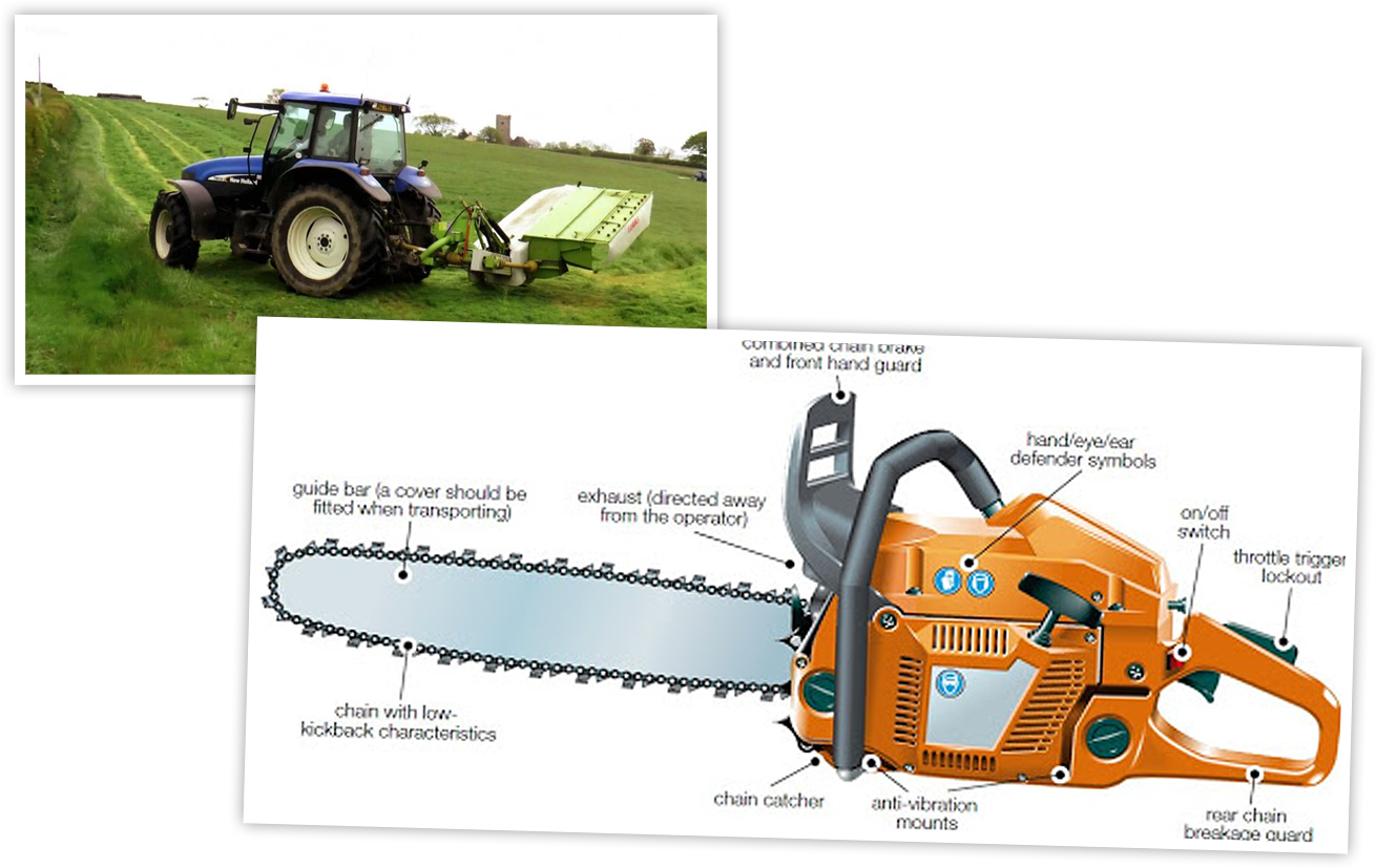
Examples of different types of cutting mechanisms
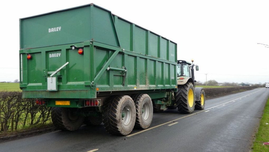
Loading capacity on land-based machinery
All machinery which carry goods have a load capacity. This is the weight of load the piece of equipment can carry.
Trailers
To find the load capacity for your axle, you should look on the trailer VIN plate or sticker that lists the VIN number. The weight rating of the axle should be listed on that same plate or sticker. Also, the axle could have a tag or plate on it that will list the weight capacity.
Terrain suitability of land-based machines
Safe and efficient use of a tractor and implement in the field can only be achieved through proper use. Certain terrains, e.g. slopes, wet, rocky, loose rock, frozen ground, slurry or FYM will affect the grip of the tractor.
The method of attaching the implement or its position can affect the centre of gravity of the tractor and the traction (grip).
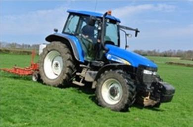
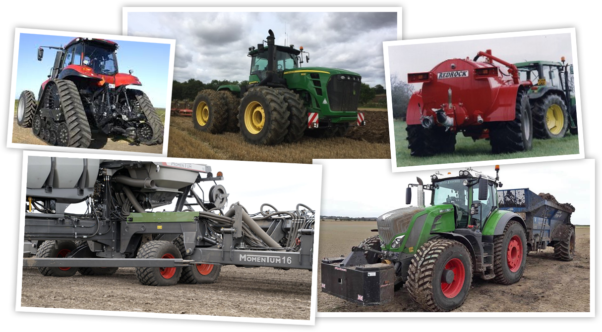
How are machines adapted to difficult terrain?
Tyres or tracks.
Safety features on land-based machines
Moving machinery can cause injuries in many ways:
- People can be struck and injured by moving parts of machinery or ejected material. Parts of the body can also be drawn in or trapped between rollers, belts and pulley drives.
- Sharp edges can cause cuts and severing injuries, sharp-pointed parts can cause stabbing or puncture the skin, and rough surface parts can cause friction or abrasion.
- People can be crushed, by parts or between parts moving together.
- Parts of the machine, materials and emissions (such as steam or water) can be hot or cold enough to cause burns or scalds and electricity can cause electrical shock and burns.
- Injuries can also occur due to machinery becoming unreliable and developing faults or when machines are used improperly through inexperience or lack of training.
Examples of safety features on land-based machines
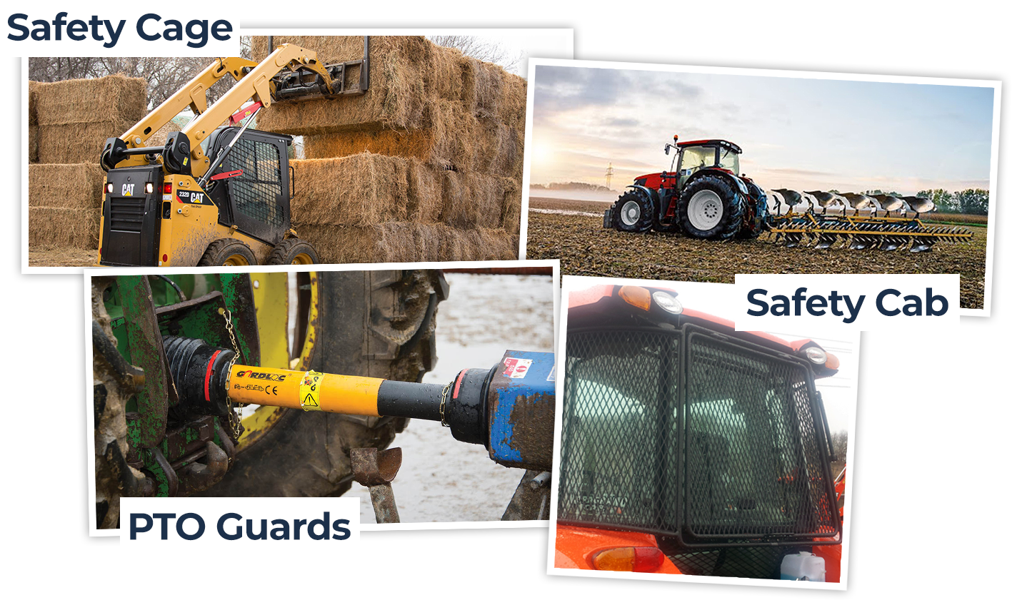
Examples of safety features on land-based machines
Conclusion
Now you should be able to:
- explain the construction and working principles of a selection of machines commonly used in their specific land based industry
- demonstrate knowledge of how they work
- give examples of performance parameters.